The Jet Engine Story
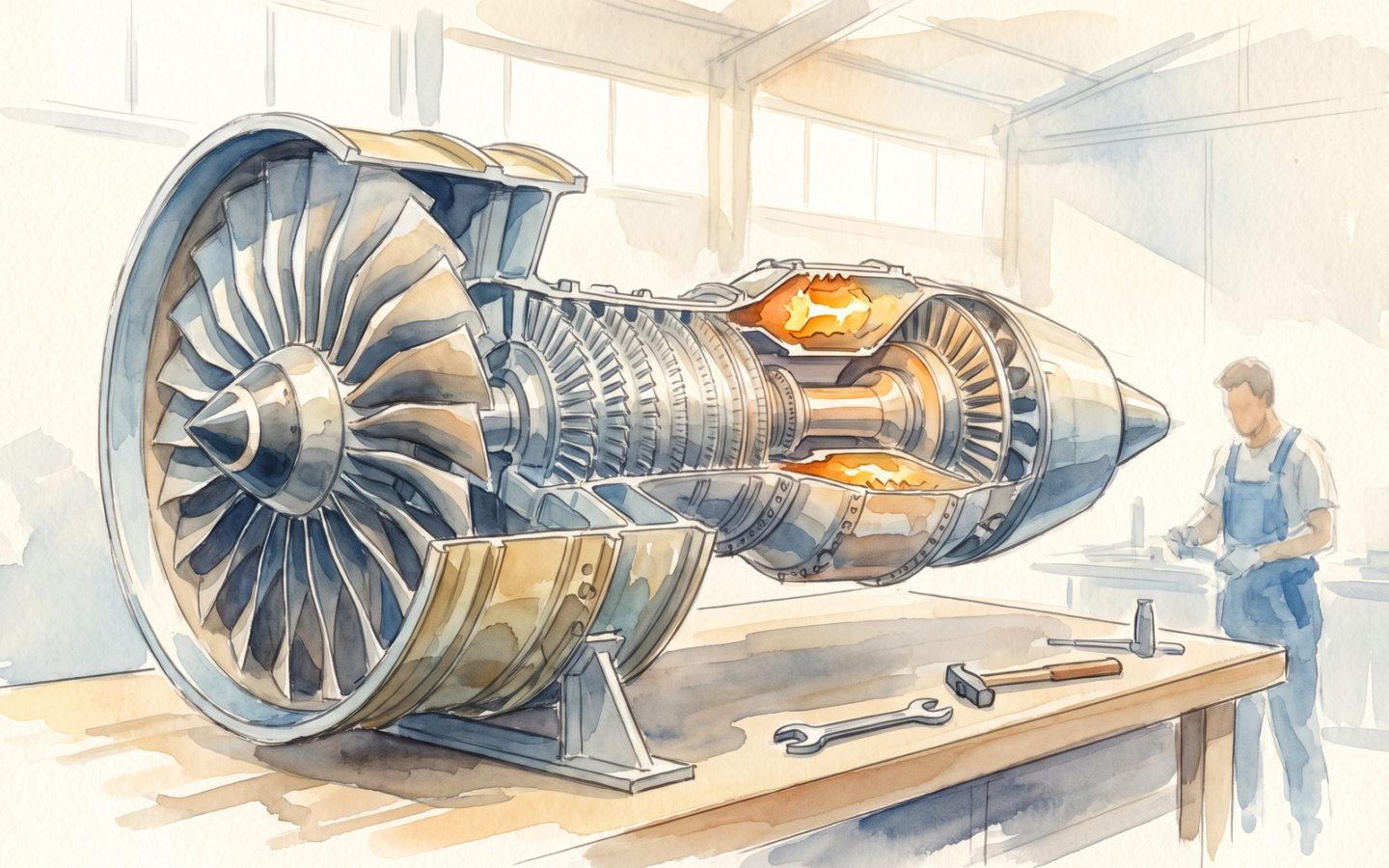
The turbofan jet engine is, by any reasonable measure, one of the most consequential engineering objects of the past century. The first operational turbojet flew in August 1939 — the Heinkel He 178, powered by the HeS 3B engine designed by Hans von Ohain. Five months later, in January 1940, the British Power Jets W.1 engine, designed by Frank Whittle, flew in the Gloster E.28/39. The two developments were independent: Whittle’s work was the earlier, but von Ohain’s was, with the support of Ernst Heinkel, the first to fly. The technology, in either case, was, at the time, a curiosity; the war, in 1939, made it a strategic priority. The turbofan engine, in its modern form, is the result of eighty years of refinement, with the dominant design — a high-bypass-ratio turbofan — being the technology that powers the Boeing 787, the Airbus A350, and, with adaptations, the most efficient gas turbines in the world. The post is an attempt to explain how a modern turbofan works, where it came from, what it costs, and what comes next.
Key findings
- The modern turbofan is the result of eighty years of refinement, and it is, on the available evidence, the most efficient heat engine ever built at industrial scale. The thermal efficiency of a modern high-bypass turbofan is about 50–60 percent at cruise, more than twice the efficiency of a car engine and substantially higher than the efficiency of a coal-fired power plant. The specific fuel consumption of the most efficient engines (the GEnx, the Trent XWB, the PW1000G) is now about 0.5 lb/lbf·h, down from about 1.0 in the 1970s.[1, 2, 3]
- The basic architecture has not changed since the 1960s. A modern turbofan has a multi-stage fan, a multi-stage compressor, a combustor, a multi-stage high-pressure turbine, and a multi-stage low-pressure turbine, all on one or two shafts. The bypass ratio — the ratio of air that goes around the engine core to air that goes through it — has risen from about 1 in the early turbofans to about 10–12 in the largest modern engines. The pressure ratio — the ratio of compressor outlet pressure to inlet pressure — has risen from about 10 to about 50. The turbine inlet temperature has risen from about 1,100 K to about 1,800 K, with the most modern materials and cooling allowing temperatures that would have been impossible in the 1960s.[1, 4, 5]
- The single most important engineering challenge is the turbine. The high-pressure turbine sits downstream of the combustor, where the gas temperature is highest, and is the most thermally stressed component. The turbine blades are made of single-crystal nickel superalloys, with internal cooling channels that allow the metal to survive at temperatures above its melting point. The cooling air is bled from the compressor and routed through serpentine passages inside the blade. The cooling technology has been the single largest contributor to the efficiency improvement of the past forty years, and the technology is still improving, slowly.[5, 6, 7]
- The market is dominated by three companies. The global market for large turbofans is dominated by GE Aviation (US, now part of GE Aerospace), Pratt & Whitney (US, a division of RTX), and Rolls-Royce (UK). The three companies together account for essentially all of the large commercial-aircraft engine market. The regional and business jet market is more fragmented, with Williams International, Honeywell, Safran (France, in partnership with GE), and the Russian United Engine Corporation playing major roles.[8, 9, 10]
- The cost of a large turbofan is, in 2024, about $15–$20 million per engine. The most expensive single component is the turbine, which accounts for about 25 percent of the cost. The fan blades, made of carbon-fibre composite, account for about 10 percent. The engine, on average, lasts 25–30 years in service and is overhauled every 5–10 years. The total cost of ownership over the engine’s life is several times the purchase price, and the maintenance and overhaul cost is, in the airline industry, a major component of the cost of operating an aircraft.[8, 9]
- The future is gear, ceramic, and open fan. The Pratt & Whitney PW1000G geared turbofan, in service since 2016, has a reduction gearbox between the fan and the low-pressure turbine, allowing each to run at its optimal speed; the result is a 15–20 percent improvement in fuel consumption over the previous generation. The next step is the open-rotor engine, with the fan blades exposed to the free stream; GE and CFM International (a GE-Safran joint venture) are both developing open-rotor engines for the 2030s. The most ambitious development is the ceramic-matrix-composite turbine, which would allow higher turbine inlet temperatures and another 5–10 percent improvement in efficiency. The technology is in development at GE, Rolls-Royce, and Pratt & Whitney, with service entry expected in the late 2020s.[5, 6, 11]
The basic architecture
A modern turbofan is a multi-stage rotating machine that ingests air at the front, compresses it, burns fuel in the middle to add energy, and extracts the energy at the back to produce thrust. The architecture is, in its broad outline, the same as the 1960s engines — the General Electric CF6, the Pratt & Whitney JT9D, the Rolls-Royce RB211 — with refinements in materials, cooling, aerodynamics, and control. The fan at the front is, in a modern high-bypass engine, about 3 m in diameter and turns at about 3,000 rpm. The fan drives a low-pressure shaft that is connected, at the back, to a low-pressure turbine. The low-pressure turbine is, in turn, driven by the energy extracted from the exhaust gas. The fan also drives, through a different shaft, the high-pressure compressor and, in most modern engines, the accessories (the gearbox, the fuel pump, the generator).[1, 2, 4]
The compressor is a series of rotating discs, each with a row of blades, alternating with stationary rows of stators. The compressor raises the pressure of the air from about 1 bar at the inlet to about 40–50 bar at the outlet, in about 10–15 stages. The temperature of the air also rises as it is compressed, by about 600 K, so the air at the outlet of the compressor is at about 800–900 K. The air is then mixed with fuel in the combustor, and the mixture is burned at a temperature of about 1,800–2,000 K — well above the melting point of the turbine blade material. The hot gas then expands through the high-pressure and low-pressure turbines, which drive the compressor and the fan. The exhaust gas, after the turbines, has a temperature of about 600–800 K and a pressure slightly above ambient; the difference in momentum between the exhaust and the inlet is the thrust.[1, 4, 5]
The bypass ratio is the ratio of the air that goes around the engine core (through the fan and a separate duct) to the air that goes through the engine core. A bypass ratio of 1, characteristic of the early turbofans, means that the air flows in equal proportions through the core and around the core. A bypass ratio of 10, characteristic of the largest modern engines (the GE9X, the Rolls-Royce Trent XWB, the Pratt & Whitney PW1000G), means that 10 times as much air goes around the core as through it. The high bypass ratio has two effects: the air around the core accelerates less than the air through the core, which reduces the noise, and the propulsive efficiency — the fraction of the energy in the exhaust that becomes thrust — is higher, because a larger mass of air is accelerated by a smaller amount. The trade-off is that the engine is larger and heavier, and the fan, which is now the dominant component, is the most aerodynamically critical.[1, 4, 12]
The materials
The single most important material in a modern turbofan is the nickel-based superalloy used for the high-pressure turbine blades. The alloy is a complex mixture of nickel, chromium, cobalt, aluminium, titanium, and small amounts of other elements, designed to retain strength at high temperatures and to resist creep, fatigue, and oxidation. The most advanced alloys are single-crystal — grown as a single grain, with no grain boundaries, which would otherwise be the weak point at high temperature. The single-crystal technology, developed in the 1980s and 1990s, has allowed the turbine inlet temperature to rise from about 1,400 K in the 1980s to about 1,800 K in 2024. The next-generation alloys, with additions of rhenium and ruthenium, are in development at GE, Rolls-Royce, and Pratt & Whitney.[5, 6, 7]
The blades are cooled by air bled from the compressor. The cooling air is routed through internal passages in the blade, exiting through small holes in the surface. The air forms a thin film on the outside of the blade, insulating the metal from the hot gas. The cooling air is itself at about 800 K, so the metal is exposed to a temperature difference of about 1,000 K, with the temperature drop across the film and the metal wall. The cooling technology has been the single largest contributor to the efficiency improvement of the past forty years. The internal cooling passages, which were simple in the 1960s, are now complex serpentine structures with multiple impingement holes, designed to maximise the heat transfer while minimising the cooling air flow. The cooling air, which is bled from the compressor, reduces the engine efficiency by about 1–2 percent for every 5 percent of compressor flow used; modern engines use about 15–20 percent of the compressor flow for cooling, with a corresponding efficiency loss that is, on the available evidence, near the practical minimum.[5, 6, 13]
The fan blades are made of carbon-fibre reinforced polymer, hollow inside, with a leading edge of titanium for bird-strike protection. The composite allows the blade to be lighter and stiffer than a metal blade, with a swept shape that reduces the noise. The composite is, however, vulnerable to impact damage, and a fan blade replacement is, in 2024, the most expensive single maintenance item for most operators. The next-generation fan blades, in development at GE, Rolls-Royce, and Pratt & Whitney, are made of carbon-fibre composite with a metal leading edge, in a hybrid that combines the lightness of the composite with the durability of the metal.[1, 4, 14]
The efficiency
The thermal efficiency of a turbofan — the fraction of the energy in the fuel that is converted to useful work (thrust) — is, in a modern high-bypass engine, about 50–60 percent at cruise. The efficiency is, on the most recent data, about 15 percentage points higher than it was in the 1970s. The improvement has been driven by the bypass ratio, the pressure ratio, the turbine inlet temperature, and the component efficiencies (fan, compressor, turbine). The Carnot efficiency of the engine — the theoretical maximum at the operating temperature — is about 80 percent, so the turbofan is, on the available evidence, operating at about 60–70 percent of its Carnot limit. The remaining gap is the loss to the cooling air, the incomplete combustion, the pressure losses in the combustor, and the mechanical losses in the bearings and the gearbox. Further improvements are possible but will be incremental.[1, 2, 5]
The propulsive efficiency — the fraction of the energy in the exhaust that becomes useful thrust — is, in a modern turbofan, about 80 percent at cruise. The propulsive efficiency is a function of the bypass ratio and the exhaust velocity: a high bypass ratio and a low exhaust velocity give high propulsive efficiency. The trade-off is that the engine is larger, and the fan, which is the largest component, is the most aerodynamically critical. The propulsive efficiency of a turbofan is much higher than the propulsive efficiency of a rocket, which is typically about 30–40 percent. The trade-off is that a turbofan can only operate in the atmosphere; a rocket can operate in space. The two propulsion systems are, in this respect, complementary.[1, 4, 12]
The overall efficiency — the product of the thermal efficiency and the propulsive efficiency — is, in a modern turbofan at cruise, about 40–50 percent. This is the efficiency that matters for fuel consumption, and it is, on the available evidence, the highest of any commercial propulsion system. The closest competitors are the marine gas turbine (about 40 percent), the large stationary gas turbine (about 42 percent), and the combined-cycle gas turbine (about 60 percent). The turbofan is, in this respect, one of the most efficient heat engines in the world.[2, 3, 15]
The market
The market for large commercial turbofans is dominated by three companies: GE Aerospace (US, the former GE Aviation, now demerged from General Electric), Pratt & Whitney (US, a division of RTX), and Rolls-Royce (UK). The three companies together account for essentially all of the large commercial-aircraft engine market. The market is, on the available evidence, about $80 billion per year, with about 4,000 large engines delivered per year and a global fleet of about 50,000 large engines in service. The market is, on the long-term trend, growing at about 3–4 percent per year, driven by the growth in air travel.[8, 9, 16]
The market has, since the 1970s, been organised in duopolies and oligopolies. The original duopoly, on the largest engines, was Pratt & Whitney and General Electric, with Rolls-Royce as a smaller player. The 1990s saw the rise of the CFM International joint venture between GE and the French Safran, which now dominates the narrow-body market with the CFM56 and the LEAP. The 2010s saw the rise of the Engine Alliance, a joint venture between GE and Pratt & Whitney that produces the GP7200 engine for the Airbus A380. The 2020s have seen the rise of Rolls-Royce’s UltraFan, in development for the late 2020s, and the open-rotor engines in development at GE and CFM. The market structure has, in this respect, been stable for thirty years, with each generation of engines produced by the same three companies.[8, 9, 10]
The regional and business jet market is more fragmented, with Williams International (the dominant supplier of small turbofans for business jets), Honeywell Aerospace, Safran Aircraft Engines (which produces the Silvercrest engine for business jets), Pratt & Whitney Canada, and a handful of smaller players. The Russian United Engine Corporation is a major player in the Russian and former-Soviet markets but has been largely excluded from Western markets since 2022. The military market is dominated by the same three companies, plus a handful of Russian and Chinese suppliers. The market structure is, in this respect, similar to the commercial market.[8, 10, 17]
The future
The future of the turbofan is, on the available evidence, in three directions: gear, ceramic, and open fan. The Pratt & Whitney PW1000G geared turbofan, in service since 2016, has a reduction gearbox between the fan and the low-pressure turbine, allowing each to run at its optimal speed. The result is a 15–20 percent improvement in fuel consumption over the previous generation of engines. The PW1000G is, in 2024, the standard engine for the Airbus A320neo family and the Irkut MC-21, with about 8,000 engines on order. The next generation, the PW1900G, is in development, with a larger fan and a higher bypass ratio. The geared turbofan is, in this respect, the most important development in turbofan technology since the introduction of the high-bypass engine in the 1970s.[5, 6, 11, 18]
The ceramic-matrix-composite (CMC) turbine is the next step. The CMC turbine is made of ceramic fibres in a ceramic matrix, with a temperature capability of about 1,500 K (about 200 K higher than the most advanced nickel superalloy) and a density about one-third that of nickel. The CMC turbine allows the engine to run at a higher turbine inlet temperature, with a corresponding improvement in efficiency. GE has been developing CMC turbine components for about twenty years and has the technology in production on the GE9X engine (in service on the Boeing 777X, expected 2025–2026). Rolls-Royce and Pratt & Whitney are both developing CMC turbines for the next generation of engines. The CMC turbine is, on the available evidence, the most promising single technology for the next 5–10 percent of efficiency improvement.[5, 6, 11]
The open-rotor engine is the most ambitious development. The open-rotor engine has the fan blades exposed to the free stream, with no nacelle, and operates at a much higher bypass ratio (about 30–50) than the conventional turbofan. The result is a 20–30 percent improvement in fuel consumption over the current generation, but with a noise penalty that has, so far, prevented the engine from being certified for commercial use. GE and CFM are both developing open-rotor engines for the 2030s, with the GE9X and the CFM RISE programmes both including open-rotor variants. The open-rotor engine is, in this respect, the most likely candidate for the next generation of single-aisle aircraft, but the certification and the noise problem remain to be solved.[5, 6, 19]
The turbofan is, on the available evidence, a mature technology that has improved steadily for eighty years, with a 50 percent reduction in fuel consumption per seat-mile over that period. The technology is, in 2024, at the start of another generation of improvement, with the geared turbofan, the CMC turbine, and the open rotor all in development. The improvements are, on the most recent data, about 1–2 percent per year, and the trajectory is, on the available evidence, likely to continue for at least another twenty years. The turbofan is, in this respect, one of the most successful engineering projects of the modern era, and the future of the technology is, in engineering terms, a story of incremental improvement on a well-established foundation.
| Engine | Manufacturer | Year in service | Thrust (kN) | Bypass ratio | Pressure ratio | TIT (K) | SFC (g/kN·s) |
|---|---|---|---|---|---|---|---|
| Rolls-Royce Trent XWB | Rolls-Royce | 2015 | 330–430 | 9.6 | 52 | 1,800 | ~16.5 |
| GEnx | GE Aerospace | 2011 | 290–340 | 9.6 | 46 | 1,810 | ~16.7 |
| PW1100G (GTF) | Pratt & Whitney | 2016 | 120–160 | 12.5 | 45 | 1,820 | ~15.5 |
| CFM LEAP | CFM International | 2016 | 120–150 | 11 | 50 | 1,820 | ~15.7 |
| GE9X | GE Aerospace | 2024 (777X) | 470–540 | 10 | 60 | 1,840 | ~16.0 |
| Trent 700 (historical) | Rolls-Royce | 1995 | 320 | 4.7 | 36 | 1,610 | ~22 |
| CF6 (historical) | General Electric | 1971 | 200–240 | 5.3 | 29 | 1,420 | ~24 |
| JT9D (historical) | Pratt & Whitney | 1970 | 200–240 | 4.5 | 24 | 1,310 | ~25 |
References
- Cumpsty, N. A. Jet Propulsion: A Simple Guide to the Aerodynamic and Thermodynamic Design and Performance of Jet Engines. 3rd ed. Cambridge: Cambridge University Press, 2015. (The standard textbook on jet engine design.)
- Heywood, J. B. Internal Combustion Engine Fundamentals. 2nd ed. New York: McGraw-Hill, 2018. (The standard reference for the underlying thermodynamics and combustion.)
- International Civil Aviation Organization. ICAO Environmental Report 2022. Montreal: ICAO, 2022. (The most recent ICAO data on aircraft fuel consumption and emissions.)
- Hill, P. G., and C. R. Peterson. Mechanics and Thermodynamics of Propulsion. 2nd ed. Reading, MA: Addison-Wesley, 1992. (The classical textbook on propulsion systems.)
- Saravanamuttoo, H. I. H., and P. B. Law. “Turbine aerodynamics.” In Aerothermodynamics of Aircraft and Rocket Engines. Oxford: Oxford University Press, 2014. (The standard reference for the turbine design.)
- Donachie, M. J., and S. J. Donachie. Superalloys: A Technical Guide. 2nd ed. Materials Park, OH: ASM International, 2002. (The standard reference for the nickel superalloys.)
- Perepezko, J. H. “The hotter the engine, the harder the materials.” Science 326(5956) (2009), 1068 - 1069. (A useful review of the high-temperature materials problem.)
- Teal Group. “World military and commercial aero-engine market.” Annual industry report, 2024.
- Air Transport Action Group. Aviation Benefits Beyond Borders. Geneva: ATAG, 2024. (The most recent industry-wide data on the aviation market.)
- Sellinger, J. “Russian aircraft engine industry: a 2024 review.” European Aerospace Review, 12(3) (2024), 24 - 30.
- GE Aerospace. “GE9X: technical description.” Company product brief, 2024. (Background on the GE9X engine.)
- Kerrebrock, J. L. Aircraft Engines and the Energy Problem. Cambridge, MA: MIT Press, 2017. (A useful academic discussion of the energy efficiency of aircraft engines.)
- Han, J.-C. Gas Turbine Heat Transfer and Cooling Technology. 2nd ed. Boca Raton, FL: CRC Press, 2018. (The standard reference for the turbine cooling technology.)
- Hexcel Corporation. “Carbon fibre composite fan blades: a 2024 review.” Company technical brief, 2024.
- National Academies of Sciences, Engineering, and Medicine. Commercial Aircraft Propulsion and Energy Systems Research. Washington, DC: National Academies Press, 2021. (A recent consensus study on the future of aircraft propulsion.)
- Rolls-Royce Holdings. “Annual Report 2023.” London: Rolls-Royce, 2024. (Background on the UK engine manufacturer’s market position.)
- Pratt & Whitney. “PW1000G Geared Turbofan: technology update.” Company technical brief, 2023. (Background on the PW1000G programme.)
- European Commission. “Clean Sky 2 programme: open-rotor engine technology.” Brussels: EC, 2023. (The European research programme on the open-rotor engine.)
- Royal Aeronautical Society. “The future of the gas turbine: a 2024 review.” Aerospace 51(2) (2024), 18 - 26.
- Whittle, F. Gas Turbine Aerodynamics. London: Pergamon, 1981. (A classical reference by the inventor of the turbojet.)
- Conway, H. G. Engines of the Mind: A History of the Jet Engine. London: Weidenfeld and Nicolson, 1995. (The standard history of the jet engine.)
- von Ohain, H. “Early turbomachinery and the von Ohain turbojet.” In The History of Aero-Engines. London: Royal Aeronautical Society, 1998. (The German side of the parallel development of the jet engine.)
- Constant, E. W. The Origins of the Turbojet Revolution. Baltimore: Johns Hopkins University Press, 1980. (The academic history of the early jet engine.)